

 English
 French
 German
deep groove ball bearing arrangement
Overview
Every rotating shaft needs at least two bearings. How those two bearings are positioned relative to each other: which one resists axial thrust and which one floats: determines whether the assembly runs quietly for 20,000 hours or seizes in the first 200. This guide covers the four decisions that define a deep groove ball bearing arrangement: locating vs floating, paired configurations, thermal compensation, and fit selection for the housing and shaft.
1. The One Fixed, One Free Rule
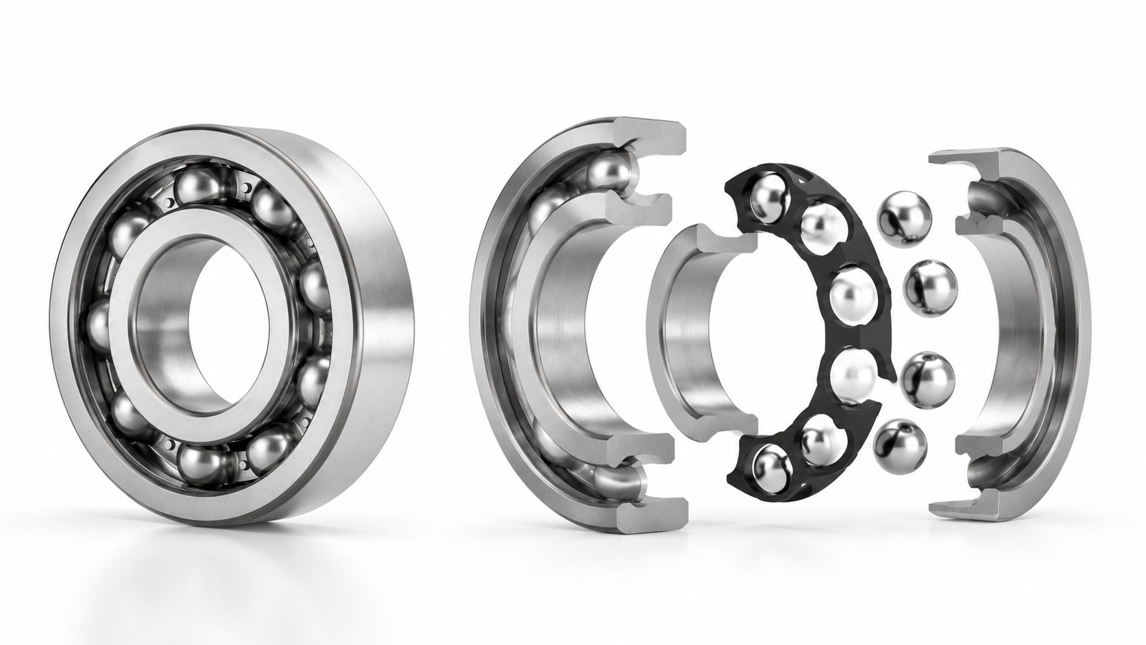
A deep groove ball bearing can handle radial loads and moderate axial loads in both directions. But it cannot handle thermal growth. When a steel shaft warms from 20 degrees C to 80 degrees C during operation, a 500 mm shaft grows by approximately 0.36 mm. If both bearings are clamped axially, that expansion has nowhere to go: the bearings overload, the preload spikes, and the raceways spall.
The solution is the locating / non-locating arrangement, also called fixed / floating. One bearing is fixed (the locating bearing). It is clamped in the housing and on the shaft, resisting all axial forces from the application: gear thrust, belt tension, impeller reaction. The other bearing is the non-locating (floating) bearing. It is clamped on the shaft but free to slide axially in the housing, absorbing the thermal expansion of the shaft without generating internal preload.
In a deep groove ball bearing arrangement, the locating bearing is typically the one closest to the load source. On a motor shaft, that is the drive-end bearing, which absorbs the belt or coupling axial pull. On a pump shaft, it is the impeller-end bearing, which takes the hydraulic thrust. The floating bearing is the opposite end. Its outer ring fits the housing with a clearance fit (G6 or H6), allowing axial displacement while maintaining radial support.
For applications with significant axial thrust, read our guide on deep groove ball bearing axial load capacity covering load ratings and limiting speeds.
Locating Bearing (Fixed)
Clamped on shaft and in housing
Absorbs all axial thrust
Closest to load source
Interference fit: both rings
Floating Bearing (Non-Locating)
Clamped on shaft only
Free to slide in housing
Absorbs thermal expansion
Outer ring: H6 or G6 clearance fit
2. Choosing Which Bearing Locates
Three factors determine which bearing takes the locating role in a deep groove ball bearing arrangement.
1
Load Direction
If an axial load pushes consistently in one direction: a helical gear mesh, a fan thrust, a belt pretension: the bearing on the loaded side becomes the locating bearing. It is clamped on both rings. The other bearing floats. This is the standard configuration for horizontal electric motors, centrifugal pumps, and conveyor drive pulleys.
For OEM bearing supply in these standard configurations, Yuanhe provides application-matched clearance and interference fits.
2
Shaft Diameter Step
When a shaft has a shoulder at one end and the shoulder is machined square to the bearing seat, that shoulder becomes the natural locating surface. The opposite end uses a locknut or snap ring. The locating bearing seats against the square shoulder. The floating bearing inner ring is retained axially, but its outer ring is free in the housing.
3
Thermal Anchor Point
In vertical shaft applications, the lower bearing is typically the locating bearing because gravity preloads it and the shaft expands upward. In a vertical pump, fixing the lower bearing keeps the impeller clearance stable. The upper bearing floats, allowing the shaft to grow axially without pushing the impeller into the volute.
3. Paired Arrangements. Back-to-Back, Face-to-Face, Tandem
When a single deep groove ball bearing cannot handle the combined radial and axial load, two bearings are paired. The three standard configurations cover different load spectra.
Back-to-Back (DB)
Outer ring faces pressed together. Inner rings face outward. Resists overturning moments better than face-to-face: the wider load center span acts like a rigid pivot. Standard choice for leadscrew supports, spindle cartridges, and robot joint harmonic drive inputs where shaft rigidity matters more than thermal accommodation.
Face-to-Face (DF)
Inner ring faces pressed together. Outer rings face outward. Load centers are closer, reducing moment stiffness but increasing tolerance to housing misalignment. Preferred when housing bore alignment is less precise or when the shaft passes through a long housing with potential bore runout. Compensates for up to 5 minutes of arc misalignment.
Tandem (DT)
Both bearings face the same direction. Doubles axial load capacity in one direction: useful for vertical shafts under heavy downthrust or unidirectional hydraulic thrust in pump shafts. Does nothing for radial load or moment stiffness. A specialized configuration: two bearings act as one thick axial bearing.
Preload in Paired Arrangements
Light axial preload (spring or precision spacer) removes internal clearance, increases stiffness, and reduces ball skidding at high speed. For deep groove ball bearings in spindle applications, a preload of 1% to 2% of dynamic load rating is typical. Higher preload increases stiffness but generates heat. At 3% Cr preload and 10,000 RPM, expect 8 degrees C to 15 degrees C temperature rise above un-preloaded operation.
4. Thermal Expansion Compensation in the Housing
The most frequent deep groove ball bearing arrangement failure is not fatigue spalling. It is thermal lock. The shaft heats faster than the housing. The inner ring expands more than the outer ring. Internal clearance disappears. The bearing preloads itself until the balls skid, the raceways gall, and the cage fractures.
CN (Normal) Clearance
< 30°C Rise
Steel housing. Room-temperature to moderate heat. Standard for most general applications.
C3 Clearance
Aluminum Housing
15-33 microns extra slack for 25mm bore. Absorbs differential expansion. Standard for motors and pumps.
Housing material matters more than most designers realize. An aluminum housing at 80 degrees C expands approximately twice as much as a steel bearing outer ring. The housing bore grows by 15 to 25 microns, releasing the interference fit and allowing the outer ring to creep. Creeping outer rings wear the housing, generate debris, and change the bearing contact angle. The fix: specify a tighter housing fit (one grade up) for aluminum housings, or use a steel insert sleeve.
Custom bearing solutions with pre-specified housing fit and clearance eliminate outer ring creep at the design stage.
Shaft fit selection follows the same logic. The inner ring must not creep on the shaft. For rotating shafts under moderate load (P / C less than or equal to 0.05), an interference fit of j5 or k5 shaft tolerance is standard. Higher loads demand tighter fits (k5 to m5). The locating bearing inner ring is always an interference fit. The floating bearing inner ring is also an interference fit on the shaft, but its outer ring is a clearance fit in the housing.
5. Arrangement Selection Decision Matrix
Match your load, speed, and shaft orientation to the recommended configuration.
6. Common Arrangement Mistakes
Five errors that appear repeatedly in bearing failure investigations.
1
Clamping Both Bearings
The shaft grows, both bearings overload, the grease cooks. Use the fixed-floating rule. One bearing locates. One floats.
2
CN in Aluminum Housing at 80°C
The housing expands, the outer ring fit loosens, the ring creeps. Switch to C3 or use a steel insert.
3
Face-to-Face on Overhung Shaft
The close load centers amplify angular deflection. Switch to back-to-back for moment stiffness.
4
No Axial Retention on Floating Bearing
The inner ring walks off the shaft under vibration. Use a locknut or snap ring on both bearings, even the floating one.
5
Interference Fit on Both Rings of Floating Bearing
The bearing cannot slide. The outer ring needs clearance fit (H6 or G6) in the housing for the floating bearing.
7. Lubrication and Sealing in Different Arrangements
The deep groove ball bearing arrangement determines how the bearings receive lubrication. In a fixed-floating arrangement with an oil bath, the oil level should reach the center of the lowest rolling element on the locating bearing. The floating bearing may sit higher in the housing: ensure both bearings are submerged to the same level, or add oil slingers to distribute lubrication.
For OEM grease-lubricated arrangements, the locating bearing typically receives a 25% to 35% grease fill. The floating bearing gets the same treatment. In DB-paired arrangements, grease both bearings individually before assembly. Do not fill the space between paired bearings with grease: the churning losses at speed will overheat the pair. Keep the inter-bearing cavity empty.
Seal selection interacts with the floating bearing design. A floating bearing with an H6 housing fit needs the seal to accommodate the axial displacement. Rubber lip seals tolerate 0.3 mm to 0.5 mm of axial movement. For larger displacements, use labyrinth seals or V-ring seals that slide on the shaft rather than the housing.
For electric motor applications, see our article on deep groove ball bearings for electric motors covering bearing selection for NEMA and IEC frame sizes.
Frequently Asked Questions
What is the difference between a locating and a non-locating bearing? +
When should I use back-to-back instead of face-to-face paired bearings? +
What clearance should a deep groove ball bearing have in an aluminum housing? +
How much axial displacement can a floating bearing absorb? +
Does a tandem bearing arrangement work for deep groove ball bearings? +
OEM Deep Groove Ball Bearings
Need a specific bearing arrangement for your application?
Send your shaft layout, load data, and operating conditions. Our engineering team returns a bearing specification with arrangement recommendations within one business day.



Related Products