


 English
 French
 German
Crossed Roller Bearings for Linear Motion and Positioning
Positioning Stage Engineering
Linear motion stages move tools, cameras, sensors, and workpieces along a straight line with micron-level precision. They are the foundation of automated inspection systems, laser marking and engraving machines, fluid dispensing stations, and precision assembly cells. Inside each stage, the linear guide bearing determines the straightness of travel, the load capacity, and the service life before accuracy degrades. Crossed roller linear guides fill a specific niche in the linear motion landscape: high stiffness in a low-profile package with smooth, predictable motion.
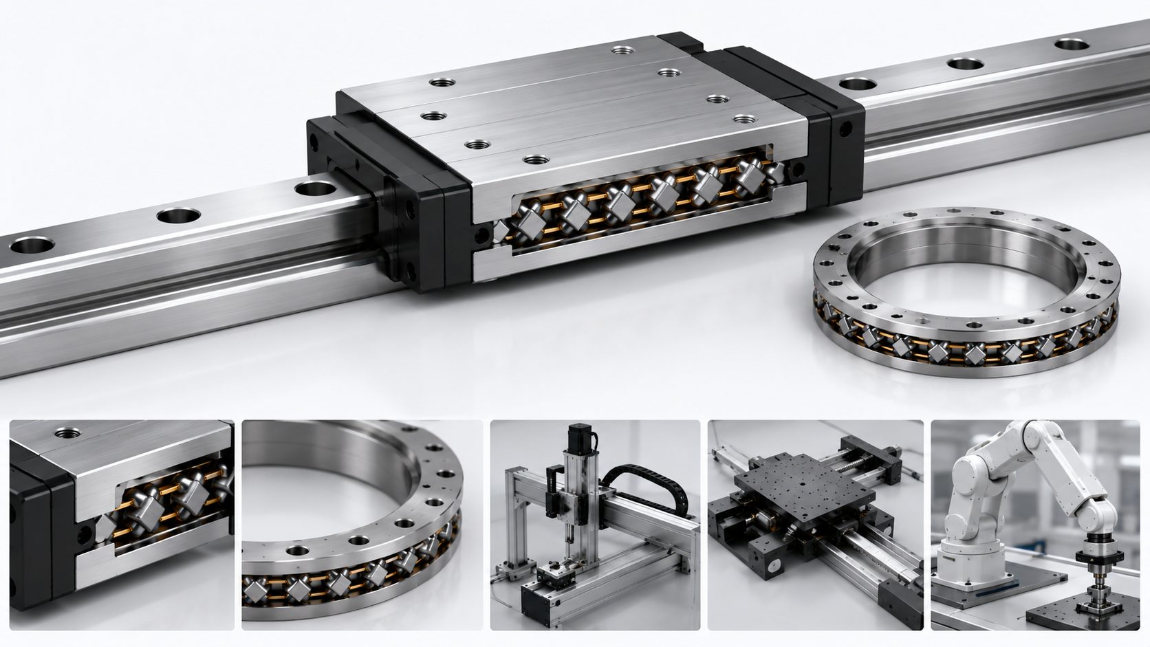
Crossed roller guides sit in the middle of the linear bearing hierarchy. Above them are air bearings for sub-micron metrology and ultra-precision machining. Below them are recirculating ball guides for general automation. Crossed roller guides offer a practical compromise: most of the straightness performance of air bearings without the need for a compressed air supply, at a cost closer to ball guides than air bearings.
How Crossed Roller Linear Guides Work
A crossed roller linear guide consists of two rails with precision-ground V-shaped raceways and a set of cylindrical rollers captured between them. The rollers alternate orientation at 90 degrees, identical to the arrangement in a rotary crossed roller bearing. One set of rollers handles vertical loads. The alternating set handles lateral loads. Both sets contribute to moment stiffness.
A cage or spacer assembly keeps the rollers evenly spaced and prevents them from skewing. As the stage moves, the cage travels at half the speed of the moving rail, a kinematic relationship that holds for all rolling-element linear guides. The available stroke length is limited by the rail length minus the cage length. For longer strokes, crossed roller guides are available in telescoping configurations with multiple rail segments.
The line contact between each cylindrical roller and the V-raceway gives crossed roller guides a significant stiffness advantage over recirculating ball guides of similar rail width. This stiffness translates directly into better straightness of travel under load because the guide deflects less when the payload weight shifts, when process forces push on the stage, or when cables and hoses pull on the moving carriage.
| Crossed Roller Guide | Recirculating Ball Guide |
|---|---|
| Line contact for high stiffness | Point contact for lower stiffness |
| Smooth, predictable rolling friction | Pulsating friction from ball recirculation |
| Limited stroke by cage length | Unlimited stroke with recirculation |
| No ball-to-ball contact noise | Ball return circuit impacts |
Straightness, Accuracy, and Friction
The straightness of a crossed roller linear guide is built into the rail grinding process. The V-raceway surfaces are precision-ground after heat treatment to remove the distortion that occurs during quenching. Typical straightness specifications for high-precision grades range from 1 to 2 micrometers of deviation per 100 mm of rail length. Over a 300 mm rail, total straightness deviation is very low when the rail is mounted on a properly prepared surface.
Friction is low, consistent, and predictable because the rollers roll without sliding at the design contact point. There are no ball return circuits, no ball-to-ball contact, and no recirculation impacts that create the pulsating friction signature of recirculating ball guides. This smooth friction profile makes crossed roller guides particularly well-suited for stages driven by linear motors or voice coil actuators.
Design Check
Load capacity is directional. Vertical load capacity is typically higher than lateral because more rollers are oriented to handle downward loads. If the stage carries a horizontally mounted camera or operates vertically, verify the lateral load rating covers the application with adequate margin for both static payload and dynamic forces.
Application Examples
Example 1 — Optical Inspection
Automated optical inspection stations use crossed roller linear stages to move cameras across circuit boards, semiconductor wafers, or precision-machined components. The straightness of travel keeps the camera within its depth of focus across the entire scan area without requiring continuous autofocus adjustment. Eliminating the autofocus step at each stop increases throughput.
Example 2 — Laser Marking
Laser marking and engraving systems use crossed roller XY stages to position workpieces under a fixed laser head. The high static stiffness of crossed roller guides prevents the stage from creeping under the small reaction forces from the laser pulse or from vibration transmitted through the machine base.
Example 3 — Fluid Dispensing
Fluid dispensing systems for adhesives, solder paste, or conformal coatings use Z-axis crossed roller stages to lower the dispensing needle. Crossed roller guides provide the low-friction, smooth motion needed at slow feed rates where stick-slip behavior would cause visible drop-size errors on the dispensed bead.
Environmental Protection Strategies
Linear guides in production environments need protection from the specific contaminants present. Bellows covers made from reinforced fabric or sheet metal protect the entire rail length but reduce the available stroke. Way wipers scrape debris off the rail surface ahead of the roller cage and work well for dry particles. Positive air purge blows clean, dry, filtered air through the guide cavity at low pressure, keeping dust out and providing a small cooling effect.
The protection method should match the dominant contaminant. Fine abrasive dust from nearby grinding operations demands full bellows because the particles are small enough to pass through wiper seals. Occasional chips from a milling operation can be handled by way wipers plus a regular cleaning schedule. Coolant spray demands full bellows with sealed ends and drainage provisions, because coolant that enters the guide cavity and mixes with the grease forms an abrasive slurry that accelerates wear.
| Method | Best For | Limitation |
|---|---|---|
| Bellows | Fine dust, coolant spray, grinding | Reduces available stroke |
| Way wipers | Dry chips, coarse debris | Not effective against liquids |
| Air purge | Airborne dust, light cooling | Not for heavy debris or coolant |
Related: Crossed Roller Linear Guides | Deep Groove Ball Bearings | Custom Manufacturing
Get a Quote
Yuanhe manufactures crossed roller linear guides in standard and custom rail lengths for positioning stage builders.
Contact us with your stroke, load, and straightness requirements for a guide selection.