

 English
 French
 German
Crossed Roller Bearings vs Harmonic Drives — What Goes Inside a Robot Joint
A six-axis industrial robot has six joints, each rotating under load. The wrist needs speed, the elbow carries weight, the shoulder does both. The bearing inside each joint determines repeatability, stiffness, and service life. Get it wrong and repeatability drifts from ±0.02 mm to ±0.08 mm after run-in. This article compares crossed roller bearing robot joint designs — crossed rollers vs harmonic drives — in real production: not spec-sheet numbers, but what happens after a year on the line.
6 axes
Standard articulated robot
±0.005 mm
Crossed roller runout spec
3–5×
Stiffness vs ball bearings
30 arcsec
Typical harmonic drive backlash
What Each Robot Joint Actually Asks of Its Bearing
From base to wrist, no two joints see the same load. The crossed roller bearing robot joint spec that works for J5 will not survive J1.
J1/J2 — Base rotation + shoulder pitch
Heaviest load, slowest speed. Overturning moment dominates. Crossed roller bearing + RV reducer is the standard stack.
J3/J4 — Elbow + wrist pitch
Medium load, medium speed. Crossed roller or angular contact + harmonic drive.
J5/J6 — Wrist rotation + end effector
Light load, high speed. Thin-section crossed roller or precision angular contact. Low inertia is the priority.
Two Bearings vs One — What Crossed Rollers Eliminate
A typical robot joint that uses ball bearings for support needs two separate bearings: one to handle the radial load from the arm weight, another to handle the axial load and overturning moment from off-center payloads. The crossed roller bearing collapses these two into one ring. Cylindrical rollers are laid perpendicular to each other in a V-shaped groove, alternating direction. Each roller makes line contact with both inner and outer rings. The result is that radial force, axial force in both directions, and overturning moment are all carried within the same bearing cross-section.
The practical benefit for robot assembly: fewer parts, shorter stack height, and no need to match preload across two separate bearings. With the RAU integrated-ring design, the inner and outer rings are one piece each — no split rings, no alignment pins, no shim stacks between ring halves. The bearing arrives as a single assembled unit.
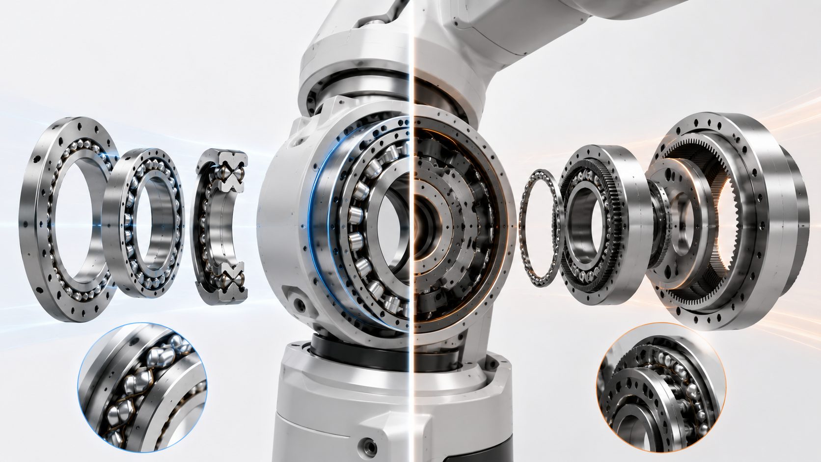
Crossed Roller Bearings — One Ring, Three Load Directions
Cylindrical rollers arranged at 90° in V-groove raceways. Each roller makes line contact with both rings. The result: radial load, axial load in both directions, and overturning moment — all carried by a single bearing. An equivalent ball bearing setup needs two separate bearings to do this.
Stiffness
3–5× higher
Overturning stiffness is 3 to 5 times that of double-row angular contact ball bearings in the same envelope. Line contact beats point contact.
Runout
≤ 0.005 mm
RAU series ships with face runout under 0.005 mm. Spacer retainers prevent roller skew, stabilizing rotational torque across the speed range.
Preload
Factory-set
RAU integrated one-piece inner and outer rings come with preload verified on a torque test stand. No shim stacks, no field adjustment.
Key Specifications
Bore range
20 mm – 200 mm
Accuracy grade
P5 / P4 / P2
Retainer
Spacer type
Material
GCr15 / 440C
Harmonic Drives — Not a Bearing, But Compared Anyway
A harmonic drive does two jobs: speed reduction and torque transmission. A wave generator deforms a flexspline, whose external teeth engage a circular spline’s internal teeth. The output side gets a high reduction ratio. Here is what most selection guides skip: the output bearing inside a harmonic drive is a crossed roller bearing. The harmonic drive is a transmission component. The crossed roller bearing is a support component. The comparison only makes sense after the reduction ratio has been locked in by the motor’s speed-torque curve.
Three harmonic drive weaknesses production engineers deal with
- Backlash — flexspline-to-circular-spline clearance typically starts around 30 arcsec and increases with wear. Once the tooth profile degrades, the joint loses repeatability.
- Stiffness — flexspline torsional stiffness does not compete with a crossed roller ring. Off-center payload deflection goes straight to TCP error.
- Fatigue — repeated flexspline deformation is the life bottleneck. Crossed roller bearings have rolling contact only. L10 life is straightforward to calculate.
Crossed Roller vs Harmonic Drive — They Are Not Substitutes
These are not interchangeable parts. A crossed roller bearing is purely a support element. A harmonic drive is a transmission with an output bearing built in. But engineers do compare them during joint design — because the harmonic drive’s output side already contains a crossed roller bearing. The question becomes: can I skip the harmonic drive and use a crossed roller bearing directly with a servo motor?
The Stiffness Difference — Measured, Not Advertised
The 3–5× stiffness figure is real, but it is not uniform across all load cases. Here is where the difference shows up and where it does not.
Pure radial load: a deep groove ball bearing and a crossed roller bearing of equivalent bore size use similar hardened steel rings and precision-ground raceways. The crossed roller bearing’s advantage is marginal in this case — both designs handle radial loads competently.
Combined load with overturning moment: this is where the crossed roller bearing pulls away. When the load vector is off-center — a workpiece clamped far from the joint face, a welding torch pushing sideways — the ball bearing’s contact ellipse elongates and the contact angle shifts. The crossed roller bearing’s line-contact geometry resists this shift. The result is 3–5× higher effective stiffness at the same moment arm. This is not a catalog number. Robot integrators measure it directly as TCP drift under load.
Quick stiffness check — when to switch from ball to crossed roller
Load eccentricity
< 1/3 pitch radius
Ball bearing acceptable
Load eccentricity
> 1/3 pitch radius
Crossed roller required
TCP drift target
Tight tolerance
Crossed roller strongly recommended
How to Decide — Three Production Scenarios
Harmonic drive already selected → crossed roller as output support
The most common case. Motor speed and torque dictate the harmonic reduction ratio. The output flange needs a bearing that rotates smoothly, resists overturning moment, and holds runout. A crossed roller bearing does exactly this. RAU integrated rings ship with factory-set preload — one less variable on the assembly line.
Direct-drive joint (DD motor) → crossed roller bearing carries everything
Some SCARA and collaborative robots use direct-drive torque motors with no reducer. The bearing is the joint’s entire support. In this configuration, a crossed roller bearing is the only sensible choice — ball bearings lack stiffness in the same envelope, and thrust-plus-radial bearing pairs exceed the available stack height.
Heavy-payload arm joints → crossed roller + RV reducer
J1 and J2 joints on high-payload robots. The flexspline in a harmonic drive may not survive the overturning moment. RV reducers have the stiffness but a larger footprint; the output bearing uses a large-diameter crossed roller ring. Here the crossed roller is selected for stiffness, not precision — a 1 mm deflection at the end of a welding robot’s arm is a scrapped part.
100 Robots, One Bearing Spec — Does Unit 100 Match Unit 1
The answer lives at the supplier end. Crossed roller bearing consistency does not come from field adjustment. It comes from two checks before the bearing leaves the factory:
Factory Check #1
Torque test stand run-in
Every RAU bearing runs on a torque test stand before shipping. Post-run-in preload is verified and stable — no secondary adjustment needed at the customer site.
Factory Check #2
Full dimensional report per unit
Bore, OD, width, face runout, radial runout — five measured values per bearing, printed on the inspection sheet. 100 robots, 100 reports. Every unit traceable to a specific batch and grinding operation.
Send your joint load data — we’ll size the bearing
Share your joint payload, speed profile, and mounting interface dimensions. Our application engineers return a crossed roller bearing selection with stiffness calculations and installation notes within two working days.