

 English
 French
 German
Crossed Roller Bearing vs Ball Bearing. Stiffness and Accuracy
Engineering Brief
Two bearings sit on a designer’s desk. One uses balls. The other uses cylindrical rollers arranged at 90 degrees. They share the same bore diameter, the same basic ring shape. Yet one will hold a robot joint to 2 micron runout for 20,000 hours. The other will chatter after 200. The difference comes down to two numbers engineers actually measure: stiffness and accuracy. This comparison covers the contact mechanics, rigidity benchmarks, runout limits, and application logic for crossed roller bearings versus standard deep groove ball bearings.
What Makes the Two Bearing Types Different
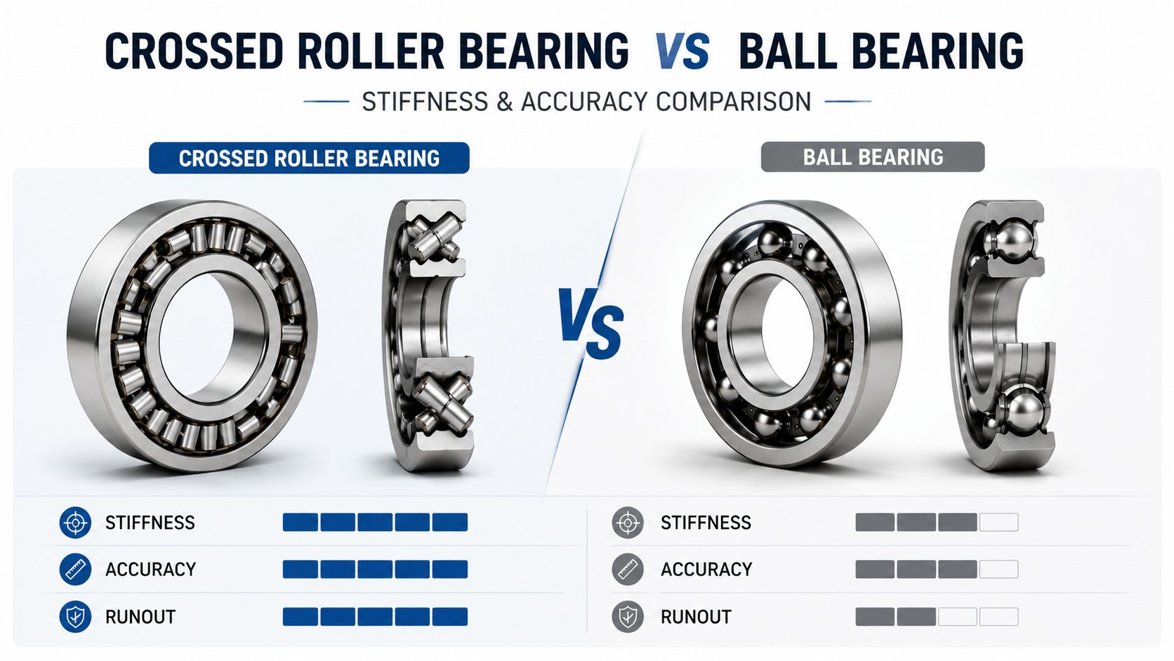
A deep groove ball bearing uses spherical balls running in a raceway groove cut to roughly 25 percent of the ball diameter. The ball contacts the inner and outer raceways at a single elliptical patch, a point contact. This geometry prioritizes low friction and high speed. The tradeoff: all the load concentrates on a few square millimeters of steel. Under heavy moment loads, the ellipse deforms, the contact angle shifts, and the shaft deflects.
A crossed roller bearing replaces balls with cylindrical rollers. Each roller is positioned at 90 degrees to its neighbor, alternating between carrying radial load and axial load. The roller contacts the raceway along a line, not a point. That line contact spreads the same load over a larger area. The crossed arrangement also gives the bearing a wider effective span between load centers. Both effects raise stiffness and lower deflection under moment loads. The cost is higher friction and lower speed, a tradeoff worth making when rigidity matters more than RPM.
Line contact over roller length
Wider load center span
Higher moment stiffness
Lower limiting speed
Point contact at elliptical patch
Narrower load centers
Lower moment stiffness
Higher limiting speed
Stiffness. Line Contact vs Point Contact
Stiffness in a bearing is the slope of the load-deflection curve. A stiffer bearing deflects less for the same load. In machine tool spindles, that difference determines surface finish quality. In robot joints, it sets the position repeatability at the end effector. In CT scanner gantries, it controls image resolution.
The stiffness difference starts with contact geometry. A ball bearing under radial load distributes force over an elliptical contact area typically less than one square millimeter for a 6205 bearing-size bearing at rated load. The crossed roller bearing distributes the same force along a line roughly equal to the roller length, typically 4 to 8 millimeters. The larger contact area reduces contact stress and produces a steeper load-deflection curve.
Ball Contact Area
< 1 mm²
at rated load (6205)
Roller Contact Length
4 – 8 mm
line contact span
Stiffness Gain
Line > Point
contact geometry effect
Moment stiffness shows an even larger gap. When a shaft applies an overturning moment, the bearing must resist angular tilt. In a ball bearing, the balls at the tension and compression sides carry the moment. In a crossed roller bearing, the 90-degree roller arrangement creates a wider load center span. Each roller pair acts like a cantilever support. The wider span converts the same roller contact stiffness into higher moment rigidity. For harmonic drive output flanges and rotary table spindles, the crossed roller bearing provides the moment stiffness that keeps the output plane flat under load.
Accuracy and Runout
Bearing accuracy is measured by runout: the deviation of a rotating surface from a true circle. For a deep groove ball bearing, ABEC grade sets the limit. ABEC-1 allows roughly 10 microns radial runout for a 25 mm bore bearing. ABEC-5 tightens that to approximately 5 microns. ABEC-7 pushes below 3 microns. These numbers come from ball roundness, raceway groove form error, and assembly clearance.
A crossed roller bearing handles accuracy differently. The cylindrical rollers are preloaded at the factory, removing internal clearance before the bearing reaches the machine builder. The preload forces each roller into firm contact with both raceways, eliminating the free play that causes runout in a clearance-fitted ball bearing. The bearing rotates around the geometric center of the ring set without the radial oscillation that ball bearings show when load direction changes.
Key Insight
A preloaded crossed roller bearing eliminates internal clearance at the source. No radial clearance to oscillate, no assembly-dependent runout band. The bearing starts its working life at the accuracy the application demands. The opposite of a clearance-fit ball bearing, where the machine builder sets final accuracy during mounting.
Factory preload also removes the assembly variable. With a ball bearing, final runout depends on how the bearing is fitted to shaft and housing. An interference fit 5 microns tighter than specified reduces internal clearance and improves runout. A fit 5 microns looser increases it. The crossed roller bearing arrives as a preloaded unit. Runout is set at the factory and does not change with mounting fit, provided mounting surfaces are flat and parallel. This repeatability matters in precision automation where every micron of position error shows up in the final product.
Where Each Type Wins
One bearing is not better. One bearing matches the load spectrum.
| Application | Demand | Best Choice | Why |
|---|---|---|---|
| Robot joint, harmonic drive | Moment stiffness | Crossed Roller | Line contact resists overturning |
| CNC rotary table spindle | Stiffness, runout | Crossed Roller | Single bearing for combined load |
| CT scanner gantry | Runout, smoothness | Crossed Roller | Micron runout for image quality |
| Electric motor, 1,800 RPM | Speed, radial load | Ball Bearing | Point contact for sustained speed |
| Conveyor pulley | Cost, sealing | Ball Bearing | Low cost-per-load, 2RS sealed |
| Pump shaft, 3,600 RPM | Speed + axial | Ball Bearing | Axial thrust at motor speed |
| Semiconductor wafer handler | Cleanroom, compact | Crossed Roller | Thin-section saves Z-height |
When to Choose Crossed Roller Bearings
Three conditions push the decision toward a crossed roller bearing over a deep groove ball bearing.
Stiffness Requirement
Sub-10 micron deflection under moment load demands line contact and wide load center span. Robot joints, machine tool rotary axes, optical positioning stages.
Runout Budget
Tight system runout budget with assembly variables to minimize. Factory-preloaded unit replaces shaft-fit, housing-fit, and clearance-selection variables.
Space Constraint
Limited Z-height or radial envelope. One crossed roller bearing replaces two angular contact bearings plus spacer and preload hardware. Wafer stages, optical tables, compact robot wrists.
The speed penalty is real. Crossed roller bearings run slower than equivalent-bore ball bearings. For applications above 1,000 RPM, a deep groove ball bearing is the correct starting point. Below 1,000 RPM where rigidity or runout dominates, the crossed roller bearing is the default precision solution.
Frequently Asked Questions
Why are crossed roller bearings stiffer than ball bearings? +
Does a crossed roller bearing need to be mounted in pairs? +
What is the speed limit for crossed roller bearings? +
Can a crossed roller bearing replace a ball bearing in an existing design? +
How is accuracy measured for crossed roller bearings? +
Precision Crossed Roller Bearings
Need a stiffness and accuracy comparison for your design?
Send load data, envelope dimensions, and accuracy requirements. Yuanhe engineering returns a side-by-side analysis with part numbers and lead times.