

 English
 French
 German
Crossed Roller Bearings for CNC Rotary Tables
A CNC rotary table bearing does two jobs at once. It spins the workpiece under the spindle, and it holds the workpiece dead level while the tool cuts. Any angular deflection at the bearing shows up as a taper or step on the finished part. Crossed roller bearings solve this with line-contact rollers in a single ring that carries the cutting force, the workpiece weight, and the overturning moment from off-center fixturing in the same motion cycle. This guide covers how to size crossed roller bearings for CNC rotary tables, the four load components that drive the selection, and the installation sequence that preserves factory-set runout accuracy.
Key Takeaways
A crossed roller bearing replaces the thrust-plus-radial bearing pair in a CNC rotary table with one preloaded ring. The line-contact rollers provide higher tilting stiffness than angular contact ball bearings in the same envelope, keeping the table face within 0.005 mm of runout after installation. The Yuanhe RAU series ships with factory-set preload verified on a torque test stand, eliminating the need for on-site shim-stack adjustment.
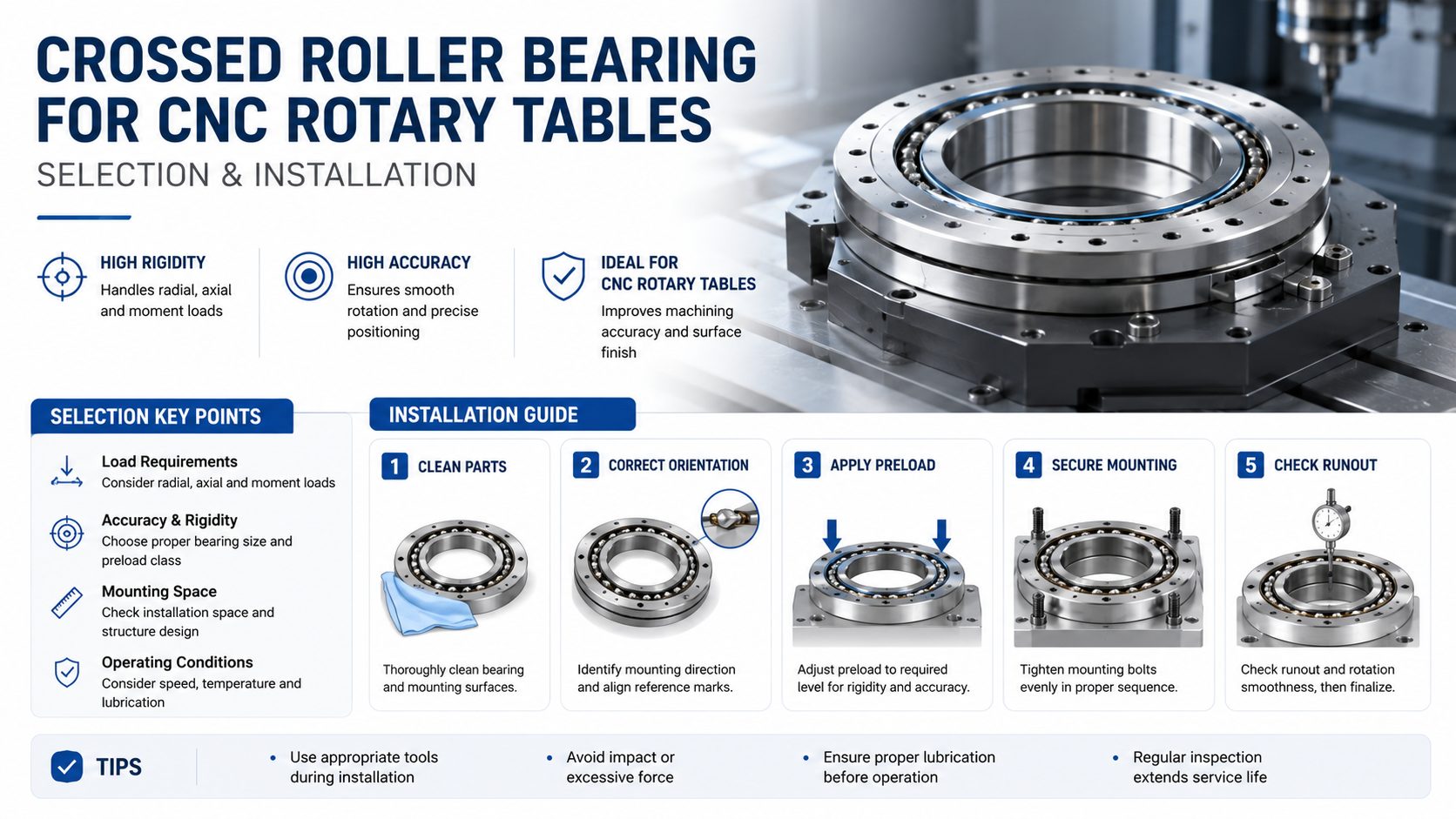
Why CNC Rotary Tables Use Crossed Roller Bearings
A conventional rotary table bearing stack uses a thrust bearing for the vertical load and a radial bearing for the side load from off-center cutting. The two bearings need a spacer ring and a housing shoulder to set the axial position of each ring. Any tolerance stack in the housing bore depth, the spacer thickness, and the bearing face parallelism compounds into angular runout at the table surface.
A crossed roller bearing eliminates the stack. Cylindrical rollers in a 90-degree alternating pattern inside a V-groove raceway carry the axial load from the workpiece weight, the radial load from the cutting tool side force, and the overturning moment from off-center fixturing inside one ring. The line contact between each roller and the raceway spreads the load over a rectangular area, giving higher static capacity and tilting stiffness than the same size angular contact ball bearing set.
Example Calculation
For a 200 mm diameter rotary table machining a 50 kg part with the tool 150 mm off-center, the bearing sees roughly 74 N-m of overturning moment. A crossed roller bearing sized for this moment holds the table face within 0.005 mm of runout. A paired angular contact set in the same envelope may deflect 2-3 times more under the same load, directly affecting the machined surface finish and dimensional accuracy.
Four Load Components That Drive Bearing Selection
Axial Load (Fa)
The combined weight of the workpiece, fixture plate, and chuck assembly pushes straight down on the bearing. Add the vertical component of the cutting force, which peaks during drilling and plunge operations. Size the bearing so Fa stays under 30% of the static axial load rating to leave headroom for the moment component.
Radial Load (Fr)
Side force from milling and contouring cuts pushes horizontally on the bearing. In a 4th-axis setup, the radial load on the rotary table bearing equals the cutting force component perpendicular to the rotation axis. For heavy roughing cuts in steel with a 12 mm end mill at 0.5 mm depth of cut, the radial force can reach 400-600 N. This is usually the smallest load component for rotary tables.
Overturning Moment (M)
Multiply the cutting force by its distance from the bearing center plane. For off-center drilling or milling, this moment tries to tilt the table. It is the dominant sizing parameter for crossed roller bearings in rotary tables. A 500 N cutting force acting 200 mm above the bearing plane produces a 100 N-m moment. Check the bearing moment rating against this peak value.
Combined Load Safety Factor
The bearing sees all three loads simultaneously. Use the equivalent dynamic load formula from the bearing catalog to combine Fa, Fr, and M into a single equivalent load. Apply a safety factor of 2-3 for machining applications where cutting forces fluctuate and occasional tool crashes are a reality. A bearing selected for the static weight alone will fail within weeks under dynamic cutting conditions.
Sizing a Crossed Roller Bearing for a Rotary Table
Start with the table diameter. The bearing bore typically runs 60-80% of the table diameter to leave enough rim thickness for the mounting bolt circle. A 250 mm rotary table normally uses a bearing with 150-200 mm bore.
Next, calculate the peak overturning moment. Place the heaviest workpiece at the worst-case off-center position, add the cutting force at the tool contact point farthest from the bearing center, and multiply by the vertical distance from cutting plane to bearing center. Compare to the bearing static moment rating with a safety factor of 2 or higher.
Then check the axial and radial load ratings independently. The bearing load ratings depend on the number of rollers and the roller diameter. A 200 mm bore crossed roller bearing typically has a static axial load rating in the range of 80-150 kN and a static moment rating of 2-5 kN-m. Exact values come from the bearing catalog for the specific series and roller complement.
Finally, define the accuracy grade. For a CNC rotary table that positions to 0.001 degrees, the bearing runout becomes the floor on achievable accuracy. Specify radial and axial runout tighter than the table positioning tolerance. A bearing with 0.005 mm radial runout and 0.010 mm axial runout supports table positioning to roughly 10 arc-seconds on a 200 mm diameter table. Tighter runout requires a higher accuracy grade, which increases cost but eliminates the bearing as the limiting factor in the machining accuracy chain.
Installation Sequence for a Crossed Roller Bearing in a Rotary Table
Clean the mounting surfaces
The housing bore and shaft shoulder must be free of burrs, chips, and cutting fluid residue. Even a 0.01 mm particle under the bearing ring distorts the raceway and increases runout. Wipe both surfaces with a lint-free cloth and a light solvent. Do not use compressed air, which can drive debris into the bearing.
Check housing bore geometry
Measure the bore diameter at three axial positions and the bore roundness at the bearing seat location. The housing bore tolerance should match the bearing outer ring tolerance, typically H6 or H7 for the housing and h5 or h6 for the shaft. A housing bore that is too tight pinches the outer ring and increases preload beyond the factory setting.
Press the outer ring into the housing
Apply even pressure around the ring face using a press plate that contacts the full ring circumference. Never hammer on one side of the ring, which brinells the raceway at the roller contact points. For light interference fits, warming the housing to 80-100 degrees C expands the bore enough to drop the bearing in by hand.
Mount the inner ring onto the shaft
The inner ring typically has a light interference fit on the shaft. Use a press or a threaded nut with a face washer to draw the ring onto the shaft shoulder. Rotate the bearing by hand after each quarter-turn of the nut to check for binding. The starting torque should stay within the range printed on the bearing inspection report.
Bolt the table faceplate to the inner ring
Tighten the faceplate bolts in a star pattern in three stages: 30%, 60%, and 100% of final torque. Measure table face runout with a dial indicator at four points after full tightening. If runout exceeds the bearing specification, loosen and re-torque, checking for uneven bolt stretch or debris trapped between the faceplate and the inner ring.
Common Installation Pitfalls
Yuanhe RAU Series for CNC Rotary Table Applications
The Yuanhe RAU series crossed roller bearings ship as integrated units with inner ring, outer ring, and crossed rollers preloaded at the factory. Each bearing arrives with a measured starting torque value and runout data on the inspection report. No spacer rings, no shim packs, no on-site preload adjustment. The integrated design means the rotary table builder machines one housing bore and one shaft shoulder, then drops the bearing in.
RAU bore diameters from 50 mm to 200 mm cover most CNC rotary table sizes from benchtop 4th-axis units to full-size horizontal machining center tables. Material is GCr15 bearing steel (equivalent to AISI 52100), through-hardened to 58-62 HRC with raceways ground to sub-micron surface finish. ISO 9001:2015 certification covers forging, heat treatment, grinding, and assembly.
For rotary table OEMs and machine builders developing new indexing or contouring axes, Yuanhe provides application engineering support including load spectrum analysis, bearing life calculation under the specific cutting duty cycle, and housing fit recommendations. 12,000+ OEM projects across 500+ B2B clients provide the data to match a bearing to a rotary table requirement before the first housing is machined.
FAQ