


 English
 French
 German
Crossed Roller Bearings in Semiconductor Manufacturing
Crossed roller bearings semiconductor manufacturing pushes motion control to its physical limits. Wafer handling robots position 300 mm silicon wafers with alignment errors measured in micrometers. Lithography stages move reticles through scanning motions at extreme accelerations. Inspection systems image features smaller than the wavelength of visible light. Every motion axis in these machines depends on bearings that deliver stiffness, accuracy, and particle-free operation in cleanroom and vacuum environments.
Crossed roller bearings appear in three critical areas of semiconductor equipment: wafer handling robot arms that transfer wafers between process chambers, XY positioning stages that scan wafers under inspection optics, and the vertical Z-axis of lithography wafer stages that control focus to within a few nanometers. Each application has a distinct set of requirements that crossed roller bearings meet better than alternative bearing types, primarily due to the combination of high stiffness in a thin cross-section and smooth, predictable motion without pulsating friction.
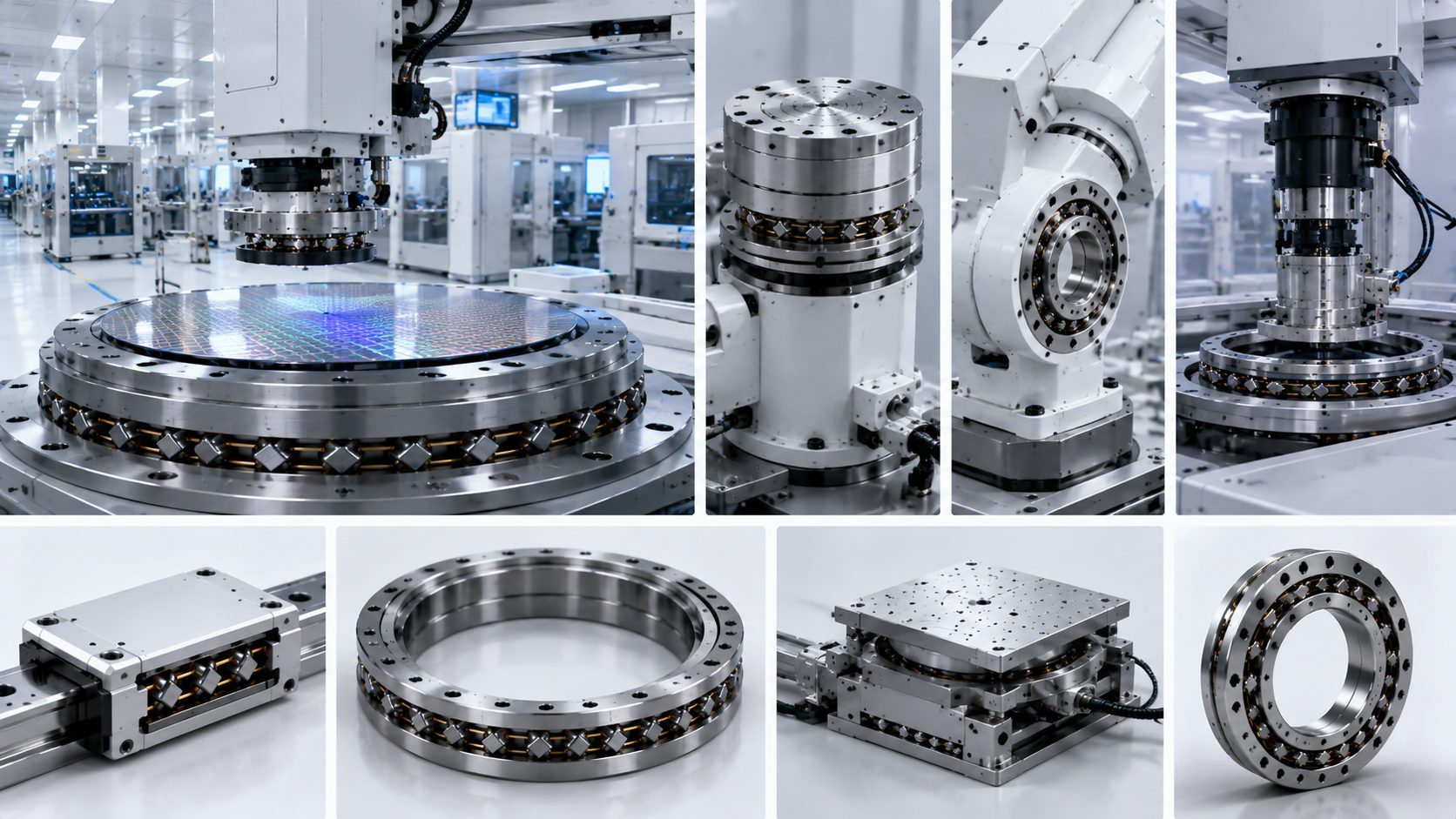
SPECSpecification Snapshot
| Parameter | Specification |
|---|---|
| Wafer Size | 300 mm |
| Positioning Alignment | Micrometer level |
| Stage Straightness | Sub-micron over 300 mm travel |
| Particle Emission | Below ISO Class 1 |
| Z-Axis Focus Resolution | Nanometer level |
| Thin Section (vs angular contact) | 8 mm vs 25 mm stack height |
APP 01Wafer Handling Robot Arms
A wafer handling robot inside a vacuum cluster tool picks up a 300 mm wafer from one process chamber and places it into the next. The arm joints use crossed roller bearings for the shoulder, elbow, and wrist pivots. Each joint needs high stiffness in a thin cross-section because the arm must fit through narrow slit valves between chambers. The slit valve opening may be only narrow, leaving very little room for the bearing and its housing. A crossed roller bearing that is 8 mm thick can provide the same moment stiffness as a pair of angular contact bearings that would require 25 mm or more of stack height.
The bearing handles a moment load created by the extended arm holding a wafer. At full extension, a wafer handling arm can reach several hundred millimeters from the shoulder pivot. A 300 mm silicon wafer weighs about roughly 130 grams, and the arm itself adds another a substantial amount. Multiply that by the 800 mm reach and the moment at the shoulder bearing is substantial. A crossed roller bearing resists this moment without needing a second bearing spaced apart, saving height in the joint stack-up and reducing the number of components that must be assembled in a cleanroom.
VACUUM
Vacuum Compatibility Is Non-Negotiable
Standard bearing grease outgasses under high vacuum and the volatile compounds condense on the wafer surface, creating defects. Crossed roller bearings for vacuum robots use low-vapor-pressure perfluoropolyether grease or solid lubricant coatings such as tungsten disulfide or molybdenum disulfide. The cage material also matters: stainless steel or PEEK cages avoid the outgassing issues of standard glass-fiber-reinforced polyamide cages. A single bearing with the wrong cage material can raise the chamber base pressure enough to affect process quality.
The robot arm bearings also see an unusual duty cycle. The arm may wait in one position for several minutes while a process runs, then execute a rapid sequence of moves to transfer the wafer in under ten seconds. During the idle period, the lubricant can drain away from the contact zone under gravity. When the next move starts, the bearing experiences a brief period of boundary lubrication before the rolling motion redistributes the lubricant. Bearings for this duty cycle need lubricants with good channeling characteristics that stay in the contact zone even during extended idle periods.
APP 02XY Inspection Stages
Wafer inspection systems scan the wafer surface for defects using high-resolution optics. The XY stage moves the wafer under a fixed optics column in a raster pattern. Straightness of motion is a top-level specification: the stage must not deviate from a straight line by more than a few hundred nanometers over a 300 mm travel. Any deviation shows up as a focus error because the depth of field of the inspection optics is measured in nanometers at the resolutions used for sub-10-nanometer defect detection.
Crossed roller linear guides used in these stages provide sub-micron straightness because the rollers are precision-ground to match the raceway profile. Unlike recirculating ball guides, crossed roller guides have no ball return circuits that create pulsating friction. The motion is continuous and predictable, which matters when the inspection optics are running auto-focus algorithms that cannot tolerate sudden velocity changes. The auto-focus loop bandwidth must be higher when the stage friction is irregular, reducing the available scan speed.
CLEANROOM
Particle-Free Operation Below ISO Class 1
The guides also need to work in cleanroom conditions without generating particles. Crossed roller bearings with proper sealing and cleanroom-compatible grease can operate below ISO Class 1 particle emission limits when installed correctly. The seals must retain the grease within the bearing cavity while preventing external particles from entering. Double-lip seals with a grease reservoir between the lips are common for this application because the trapped grease acts as an additional particle barrier.
APP 03Lithography Wafer Stage Z-Axis
The wafer stage in a lithography scanner moves the wafer in six degrees of freedom. The Z-axis adjusts focus by moving the wafer up and down through a range of a few hundred micrometers with nanometer-level resolution. This axis uses a crossed roller bearing or an air bearing depending on the machine generation and the required precision. In systems using crossed roller bearings, the bearing provides both vertical guidance and tilt stiffness to keep the wafer plane parallel to the image plane throughout the exposure field.
The short stroke of the Z-axis means the bearing never sees full rotation. The motion is typically a sinusoidal oscillation with an amplitude of a few hundred micrometers at a frequency of hundreds of cycles per second. This small-amplitude oscillation places unique demands on the lubrication. Fretting corrosion can develop at the roller-to-raceway interface if the lubricant does not replenish the contact zone between cycles. Special fretting-resistant greases with anti-wear additives address this failure mode.
Regular maintenance cycles on lithography tools include bearing inspection. Technicians check running torque and look for any increase in friction that might indicate lubricant breakdown or particle ingress. The crossed roller bearing in a lithography Z-axis may run for several years or more between replacements when maintained on schedule. The replacement cost of the bearing itself is small compared to the cost of the production downtime required to replace it, so the maintenance schedule is designed around maximizing uptime rather than minimizing bearing cost.
Related: Crossed Roller Bearings | Deep Groove Ball Bearings | Custom
Get a Quote
Yuanhe supplies crossed roller bearings with vacuum-compatible and cleanroom-grade options for semiconductor equipment builders. Contact us to discuss your motion stage requirements.