

 English
 French
 German
Crossed Roller Bearings for Robot Joints
Robot joints live under three load directions at once. The arm accelerates, the payload shifts, and the bearing inside the wrist or elbow sees radial force, axial thrust, and overturning moment in the same motion cycle. Pick the wrong bearing geometry and the joint develops backlash within weeks. Crossed roller bearings solve this with a single ring that replaces two angular contact pairs while cutting joint width by 40-60%. This guide covers how crossed roller geometry handles compound loads, where they fit inside six common robot joint architectures, and the five parameters that determine bearing size for an arm that holds positioning accuracy across its service life.
Key Takeaways
Crossed roller bearings carry radial, axial, and moment loads inside one thin-section ring. They eliminate the paired-bearing stack common in robot joints, reducing assembly parts count by half while raising tilting rigidity 3-5x over equivalently sized angular contact ball bearings. The Yuanhe RAU series integrates inner and outer rings in a single preloaded unit, cutting installation time and removing the risk of on-site preload adjustment errors.
Load Directions
3
Radial, axial, and moment in one ring
Rigidity Gain
3-5x
Over angular contact ball bearings
Joint Width Savings
40-60%
One ring replaces two bearing sets
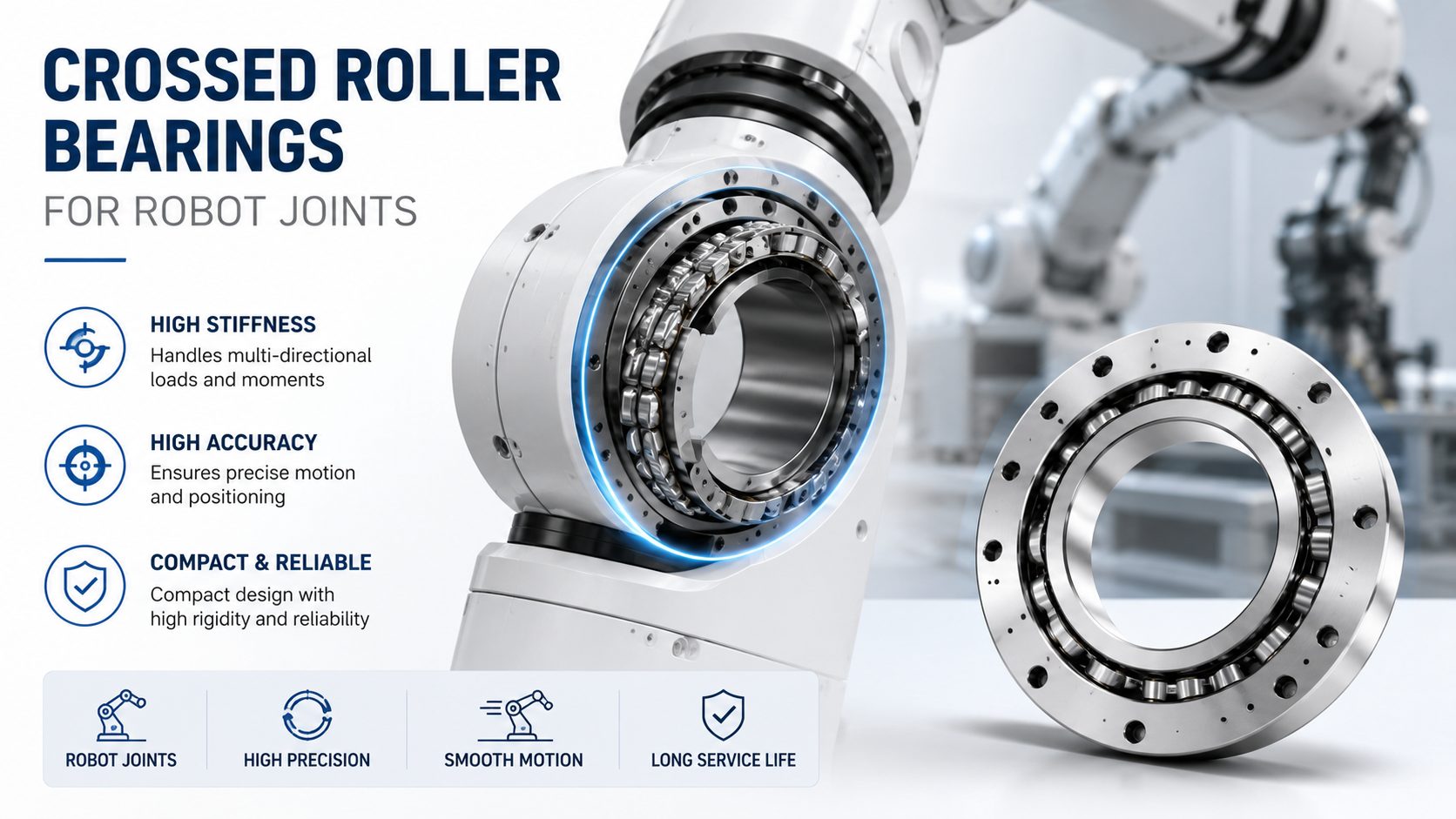
How Crossed Roller Geometry Handles Robot Joint Loads
In a conventional robot joint, two angular contact ball bearings mount face-to-face or back-to-back to handle the reversing moment that the payload creates. Each bearing carries part of the radial load and one direction of axial thrust. The pair needs a spacer ring to set preload, and the assembly stack height eats joint real estate.
A crossed roller bearing replaces this entire stack. Cylindrical rollers sit in a 90-degree alternating pattern inside a single V-shaped raceway. Every other roller runs perpendicular to its neighbor. Radial load transfers through the rollers aligned with the shaft axis. Axial thrust transfers through the rollers aligned perpendicular to the shaft axis. The overturning moment distributes across all rollers through the V-groove geometry.
The line contact between each roller and the raceway surface spreads force over a rectangle rather than a point. This gives the bearing higher static load capacity and greater tilting stiffness than a same-envelope angular contact ball set. For a robot wrist that flips a 20 kg payload at the end of a 1.2 m arm, the moment on the joint bearing is 235 N-m. A crossed roller bearing sized for this moment fits in a ring roughly half the axial length of the two-bearing alternative.
Robot Joint Types That Use Crossed Roller Bearings
Six-Axis Industrial Robot Arms
The wrist axes (J4, J5, J6) on a six-axis industrial arm are the most bearing-sensitive joints on the machine. These three axes see the full payload moment multiplied by the wrist offset distance. J5, the bending axis, is the most demanding: it must hold orientation while the arm accelerates the tool through an arc. A crossed roller bearing at J5 provides the tilting stiffness to keep the tool center point within tolerance during high-speed path moves. At J4 and J6, the same bearing type handles combined rotation and bending with zero internal clearance after preload.
Collaborative Robots (Cobots)
Cobot joints add a constraint that industrial arms do not have: the bearing must maintain low and consistent starting torque for force-sensing accuracy. A cobot joint torque sensor detects contact by measuring the current rise in the joint motor. If the bearing friction varies, the sensor cannot distinguish between a human collision and a tight spot in the bearing rotation. Crossed roller bearings with spacer-retained rollers and light preload deliver the repeatable low-friction rotation that cobot force-limited joints need. The single-ring design also simplifies the hollow-shaft routing for power and signal cables running through the joint center.
Surgical and Medical Robots
Surgical robot arms operate at the opposite end of the size spectrum. Joint bearings here might have bore diameters under 30 mm, and the motion is slow, deliberate, and must exhibit zero stick-slip. A crossed roller bearing in a surgical robot end-effector joint provides smooth sub-degree rotation while supporting the weight of an instrument cluster. The thin-section profile keeps the joint housing compact enough to fit through a trocar port or surgical access opening. Runout measured in microns matters more than load rating in these joints: crossed roller bearings consistently achieve radial runout under 0.005 mm when preloaded correctly.
Rotary Indexing Tables and End-Effector Positioners
Robot cells often pair a six-axis arm with a servo-driven rotary table that flips or indexes the workpiece between operations. The table bearing carries the workpiece weight plus the clamping force while indexing at cycle speeds. Crossed roller bearings serve as the table pivot: the large bore leaves a clear center passage for pneumatic or hydraulic lines, and the high overturning stiffness keeps the workpiece level under off-center fixturing. A 200 mm diameter crossed roller bearing in a welding positioner holds a 500 kg part within 0.01 mm of level while the table rotates 180 degrees in under 1.5 seconds.
Crossed Roller vs Other Bearing Types in Robot Joints
| Bearing Type | Moment Capacity | Joint Width | Part Count |
|---|---|---|---|
| Crossed roller (single ring) | High, line contact V-groove geometry | Minimal , one ring | 1 bearing, no spacer |
| Angular contact ball (paired) | Moderate , point contact | Tall , two bearings plus spacer | 3+ components |
| Thin-section four-point contact | Moderate , limited by ball size | Compact , single ring | 1 bearing |
| Tapered roller (paired) | High , line contact | Tall , two cones plus adjustment | 4+ components |
Each robot joint application makes a different trade-off. High-speed SCARA arms often use angular contact pairs because the axial loads dominate and the cost target is aggressive. Heavy-payload spot-welding robots lean toward crossed roller bearings for the wrist axes where the overturning moment from the welding gun cannot be absorbed by a point-contact bearing without oversizing. Collaborative robots favor crossed roller for the combined stiffness and predictable friction characteristic. The decision turns on the load spectrum the joint will see across its full duty cycle, not just the peak static condition.
Five Parameters That Determine Bearing Size for a Robot Joint
Overturning Moment (M)
Multiply payload weight by the distance from the bearing center to the payload center of mass. Add the inertial moment from joint acceleration. This is the dominant sizing parameter for wrist axes. Size the bearing to handle the peak dynamic moment, not just the static payload moment.
Axial and Radial Load Components
Decompose the payload force into radial and axial vectors based on the joint orientation at the worst-case arm pose. Crossed roller bearings carry both directions simultaneously, but the ratio affects which raceway shoulder sees peak stress. Check the bearing load ratings against both components independently.
Duty Cycle and Speed
A spot-welding robot wrist oscillates 30-60 degrees at 2-4 Hz for millions of cycles. The bearing sees fretting risk at the reversal points. A pick-and-place robot spins continuously in one direction at 60-120 RPM. The lubrication regime differs. Load rating must be derated for oscillating motion where the lubricant film never fully re-forms between reversals.
Stiffness Requirement (Deflection Under Load)
Define the maximum angular deflection the joint can tolerate at the tool point. A 0.5 mm position error at a tool 800 mm from the joint translates to a 0.036-degree angular error. Work backward to the bearing tilting stiffness needed. Crossed roller bearings provide higher tilting stiffness per gram of bearing weight than paired ball bearings because every roller contributes to moment resistance.
Envelope Constraints
Robot joint housings are diameter-constrained by the arm tube cross-section and length-constrained by the reach target. A crossed roller bearing with integrated inner and outer rings, like the Yuanhe RAU series, eliminates the separate housing shoulders and spacer rings that paired bearings need. The saved axial length can be reallocated to a larger motor or a longer reduction gear stage.
Yuanhe RAU Series Crossed Roller Bearings for Robot Joints
The Yuanhe RAU series integrates inner ring, outer ring, and crossed rollers into a single preloaded unit. No separate spacer rings, no shim-stack preload adjustment at assembly. Each bearing ships with factory-set preload verified on a torque test stand. The integrated design means the robot joint housing simply presses or bolts the bearing outer ring into a bore and clamps the inner ring to the shaft. Assembly time per joint drops from 30-45 minutes for a paired-bearing stack to under 10 minutes for a single RAU unit.
Standard RAU bore diameters range from 20 mm to 200 mm, covering the wrist and elbow axes on robots from lightweight cobots to 200 kg payload industrial arms. Each bearing undergoes 100% dimensional inspection with runout and starting torque recorded on the inspection report shipped with the order. Material is GCr15 bearing steel (equivalent to AISI 52100), through-hardened to 58-62 HRC. ISO 9001:2015 certification covers the full manufacturing process from forging to final assembly.
For robot builders developing a new joint architecture, Yuanhe provides application engineering support that includes load spectrum analysis, bearing life calculation under the specific duty cycle, and preload optimization for the target stiffness-versus-friction trade-off. 12,000+ OEM projects across 500+ B2B clients provide the application database to match a bearing geometry to a joint requirement before cutting metal on the prototype housing.
FAQ
Engineer to Engineer
Send Your Joint Load Data for a Bearing Recommendation
Share your arm configuration, payload, reach, and duty cycle. Yuanhe application engineers return a crossed roller bearing specification with load-life calculation and preload recommendation within two working days.