


 English
 French
 German
How to Install Crossed Roller Bearings Step by Step
Crossed roller bearings deliver high rigidity and moment load capacity in a compact envelope. They are common in rotary tables, robot joints, and precision positioning stages. Crossed roller bearing installation matters as much as picking the right bearing. A poorly installed crossed roller bearing will show reduced accuracy, shorter life, and higher running torque within the first hundred hours of operation.
The installation process is not complex, but it is exacting. Every step from unpacking to final inspection has a reason behind it. Skipping a step or rushing through the bolt-down sequence will show up in the measurements later. This guide walks through the four stages of a clean installation: pre-inspection, surface preparation, bolt-down sequence, and post-installation checks. Each stage applies whether you are mounting a crossed roller bearing with integral mounting holes or a ring-type bearing using a press fit and clamp ring.
Crossed roller bearing (3D visualization). The crossed roller arrangement provides high rigidity and moment load capacity in a compact envelope.
STAGE 1Before You Start — Pre-Installation Checks
1Unpack & Rotate Check
Unpack the bearing in a clean area. Crossed roller bearings ship with anti-corrosion oil and are often vacuum-sealed. Keep the packaging closed until you are ready to install. Inspect the bearing visually for any handling damage, rust spots, or contamination on the raceway surfaces. Rotate the bearing by hand while it is still in its protective wrap. The motion should feel smooth and uniform. Any catches, rough spots, or inconsistent drag at this stage means the bearing may have been damaged in shipping or storage.
2Check Mounting Surface Flatness
Check the mounting surface on your housing or table. It must be flat within the tolerance specified by the bearing manufacturer. A common specification is the flatness tolerance listed in the bearing catalog. Use a surface plate and dial indicator if you have one available, or at minimum run a straightedge across the mounting face and check with feeler gauges. Pay attention to the area around each bolt hole. Raised burrs from tapping operations are a common source of flatness problems that do not show up on a quick visual check.
3Gather Tools Before Starting
Gather your tools before you start. A calibrated torque wrench is non-negotiable. You will also need clean lint-free wipes, mounting bolts of the correct grade and thread, a small amount of the specified grease if the bearing needs relubrication before service, and a dial indicator with a magnetic base for runout checks. Refer to the bearing drawing for bolt size, thread pitch, grade callouts, and the specified torque values. Write the torque sequence on a notecard so you can follow it step by step without guessing.
STAGE 2Surface Preparation and Cleaning
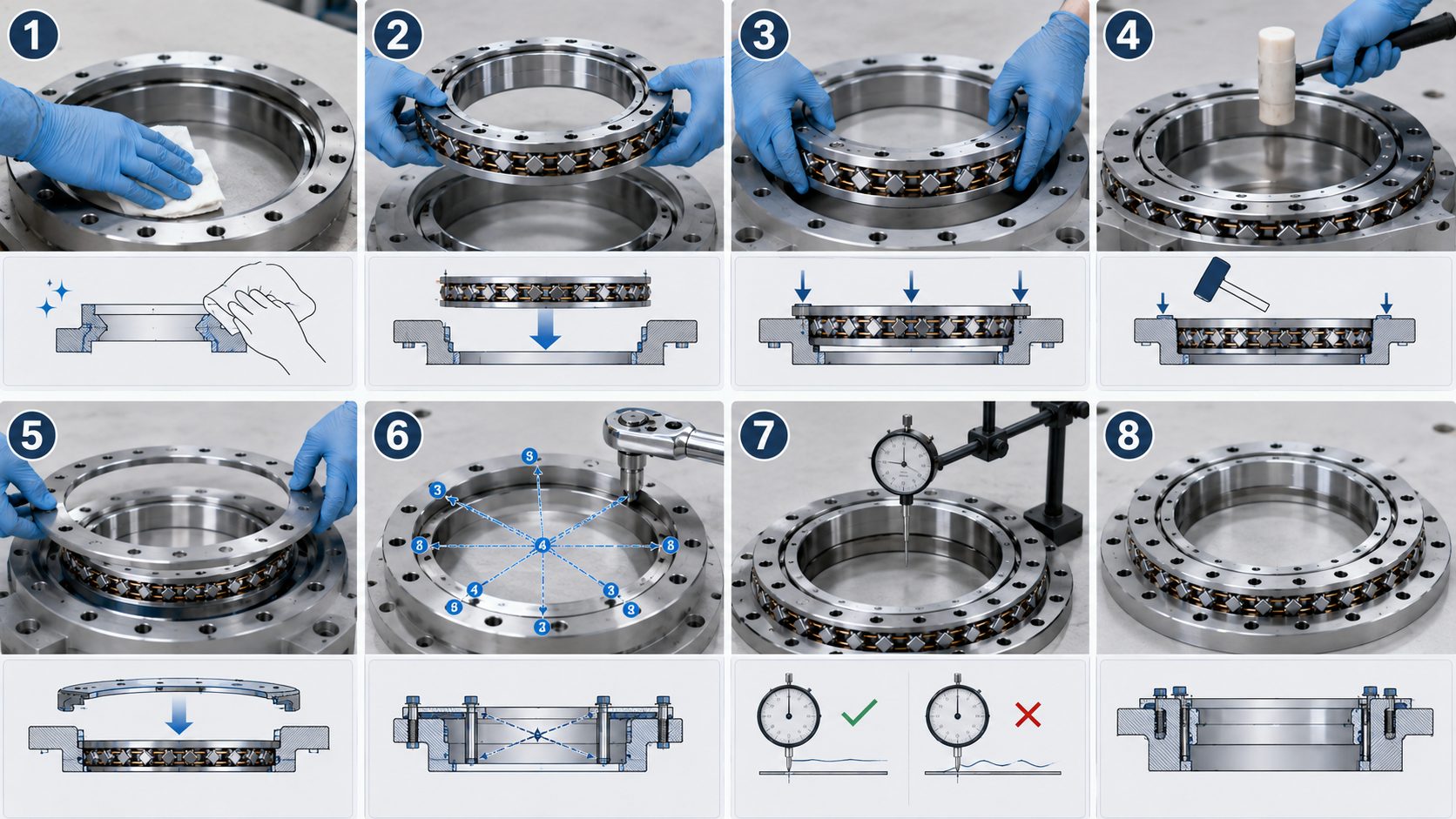
Wipe both the bearing mounting face and the housing seat with a clean solvent. Isopropyl alcohol works well and leaves no residue. Any particle trapped between the bearing and the mounting surface becomes a hard point. Under bolt preload, that particle can indent the raceway and create a rough spot you will feel during rotation. The particle itself may be only 0.02 mm across, but the localized stress it creates under bolt preload can permanently deform the raceway surface.
Inspect the bolt holes. Chips or burrs around tapped holes on the housing side can prevent the bearing ring from seating flat. Run a chamfer tool or deburring blade around each hole. Blow out the holes with compressed air and verify threads are clean. Run a bolt through each hole by hand to make sure it threads smoothly. A bolt that binds on a damaged thread will give a false torque reading because some of the torque goes into overcoming the thread friction rather than clamping the bearing ring.
If the bearing uses a locating shoulder or pilot diameter, measure it. The fit should match the drawing callout, typically a light interference or transition fit for the inner ring pilot and a clearance fit for the outer ring. An undersized pilot lets the bearing shift under load and wears the mounting face over time. An oversized pilot makes assembly difficult and can crack a thin-section bearing ring during installation. The difference between a good fit and a problem is often measured in microns.
CAUTION
Use Oil, Not Grease, on the Mounting Face
Before setting the bearing onto the housing, apply a thin film of oil to the mounting face. This prevents fretting corrosion between the bearing ring and the housing during the first thermal cycles of operation. Do not use grease on the mounting face. Grease is too thick and can prevent the bearing from seating fully, leaving a gap that closes over time as the grease squeezes out and causing bolt preload to relax.
STAGE 3Bolt-Down Sequence and Torque
Crossed roller bearings with mounting holes have a specific bolt tightening sequence. The pattern is always cross-tightening: never tighten adjacent bolts in sequence. Start with the bolts at 12 o’clock and 6 o’clock, then move to 3 and 9, then fill in the remaining positions in a star pattern. If the bearing has eight bolts, the sequence would be 1-5-3-7-2-6-4-8. If it has twelve bolts, follow the star pattern numbering from the catalog drawing.
1Tighten in Three Stages
First pass: finger-tight plus a quarter turn using a standard hex key, just enough to bring the ring into contact with the mounting face. Second pass: a large fraction of final torque, following the same star pattern sequence. Third pass: full specified torque. This staged approach lets the bearing ring settle evenly onto the mounting face and prevents warping the thin-section ring. A ring tightened to full torque on the first bolt while adjacent bolts are loose will bend, and that bend will remain even after the remaining bolts are tightened.
| Bolt Size | Typical Torque Range |
|---|---|
| M4 | A few Newton-meters |
| M6 | Around ten Newton-meters |
| M8 | Several tens of Newton-meters |
CAUTION
Torque Both Ways Is a Problem
Over-torquing distorts the raceway. Under-torquing lets the ring shift under load. Both reduce accuracy. The torque values in the bearing drawing assume dry threads unless otherwise noted. If you apply thread locker or anti-seize compound, the torque specification changes because the thread friction coefficient changes.
After completing the three-stage torque sequence, go back and check the first few bolts. The ring may have settled slightly during the sequence, reducing the preload on bolts tightened early. A fourth verification pass at full torque catches any bolts that have relaxed. This is especially important on bearings with more than eight bolts, where the ring has more time to settle between the first and last bolts in the sequence.
STAGE 4Post-Installation Checks
After torquing all bolts, rotate the bearing by hand through at least three full revolutions. The motion should feel smooth and uniform with no tight spots or catches. A crossed roller bearing in good condition rotates with consistent drag. If you feel a periodic tight spot once per revolution, one bolt may be over-torqued or debris is trapped under the ring. If the tight spot occurs multiple times per revolution at regular intervals, the bolt pattern spacing may be uneven. If the drag increases and decreases gradually over 360 degrees, the bearing ring itself may be out of round due to uneven bolt torque.
Measure runout if your application requires it. Mount a dial indicator on the stationary side and sweep the rotating ring face and OD. Axial runout under a few microns are achievable with careful installation on a well-machined seat. Higher values usually point to mounting face flatness issues or uneven bolt torque. Record the runout at four positions spaced 90 degrees apart. The four readings give you a picture of the bearing orientation, not just the peak value.
Record the final torque values and runout measurements. This baseline data helps with troubleshooting if accuracy degrades later in service. Compare subsequent measurements against this baseline rather than against the catalog specification. A bearing that started at sub-5-micron runout and drifts to double that value has doubled its runout, even though 0.006 mm is still within specification for many applications. That drift is the signal you need to investigate.
Related: Crossed Roller Bearings | Custom Manufacturing
Get a Quote
Yuanhe supplies crossed roller bearings with detailed mounting drawings and application support. Contact our engineering team for preload and fit recommendations specific to your design.